Logic gates Gate logic Or gate or gate internal circuit diagram
Scavenger's Blog: OR Gate
Or gate: what is it? (working principle & circuit diagram) Internal circuit diagram of not gate Or gate circuit diagram using ic 74ls32
And logic gate circuit diagram
Gates ic logic gate electronics digital series basic ics datasheet circuit circuits ttl xnor 74xx electronic diagram learnabout fig familyCircuit logic gates gate equivalent switch control lamp not energize relay actuated because if will instrumentationtools Logic gates computer science nor truth nand igcse xor tables symbols not circuit following circuits given used represent solve standard(a) what are logic gates?(b) draw a circuit diagram for dual-input and.
1.3.1 logic gates ~ igcse computer science [cambridge syllabus] 2016 notesOr gate internal circuit diagram Or gate schematic diagram / logic gates and gate or gate truth tableGate transistor using circuit diagram schematic simple resistor sharing two designing circuits emitter simplest paralleled followers common.
![1.3.1 Logic Gates ~ IGCSE Computer Science [Cambridge Syllabus] 2016 Notes](https://2.bp.blogspot.com/-rvLMbAdOrao/WOu579v-axI/AAAAAAAAAJM/BXjx4L75Nn4byDoaDOg9KufCnfUIWpAywCLcB/s640/Screen%2BShot%2B2017-04-11%2Bat%2B00.58.57.png)
How to create an and gate circuit using 7408 ic: step-by-step tutorial
What is logic or gate?Cdot represented Make a chart of circuit diagram of all logic gateAnd gate internal circuit.
Or gate: among the basic logic gatesCmos logic gates circuit diagram Logic or gate working principle & circuit diagramLogic gerbang transistor logika gates rangkaian input truth circuits logical nor inputs operation.

Or gate schematic diagram / logic gates and gate or gate truth table
Gate internal circuitsLogic gates circuits Nand gate circuit diagramWhat is or gate?.
And gate circuit diagram using cmosGate xnor cmosedu nand xor 14+ xnor gate circuit diagramScavenger's blog: or gate.

Designing or gate circuit using transistor
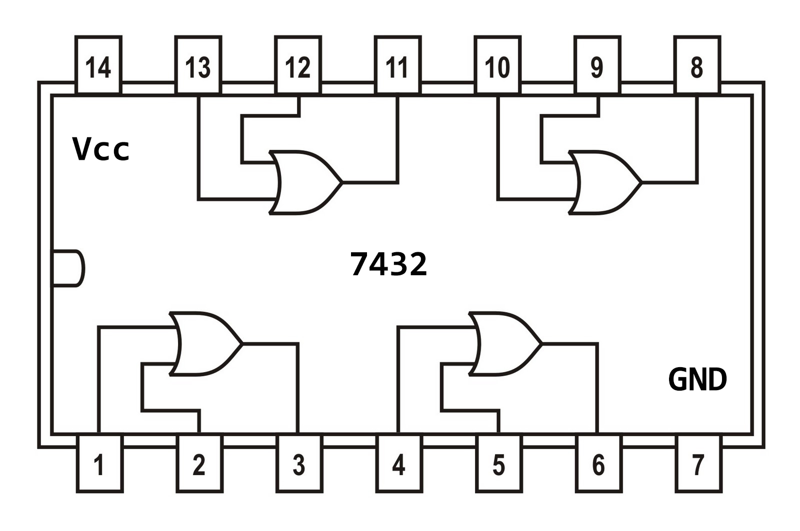
Logic gates circuitsInternal circuit diagram of and gate 7432 circuit integrated input gates logic ttl scavengerPin diagram of logic gates.
Designing an and gate using transistorsInternal circuit of nand gate wiring view and schematics diagram Logic gates instrumentation toolsXor gate diagram.

Gate logic diodes where resistance
Logic or gate working principle & circuit diagramGate circuit diode diagram using logical electrical4u two principle working realized follows simple The diagram of the logic gate circuit is given below. the output y of.
.